Information Links
Related Conferences
Current Issue Volume 10, Issue 1 - 2026
A Review on Fabrication Techniques and Applications of Cellulose-Based Biomaterials for Sustainable Environmental Remediation
Chekwube A Ezegbe1,*, Obioma R Emeka-Obi2, Kosisochukwu A Emeagwali3, Ezinne C Okorafor4, John I Osaro5, Chisom G Ezegbe6
1Department of Pharmaceutical Technology and Industrial Pharmacy, University of Nigeria, Nsukka, Enugu State, Nigeria
2Department of Haematology, School of Basic Clinical Sciences, College of Medicine, Federal University of Technology, Owerri, Imo State, Nigeria
3Department of Production Engineering, University of Sao Paulo, Cidade Universitaria, Butanta, Sao Paulo, Brazil
4Department of Pharmacology, School of Basic Clinical Sciences, College of Medicine, Federal University of Technology, Owerri, Imo State, Nigeria
5Department of Chemistry, Science and Technology, Federal University of ABC, Avenida dos Estados, 5001, 09210-580, Santo Andre, Sao Paulo, Brazil
6Department of Information Engineering, Federal University of ABC, Avenida dos Estados, 5001, 09210-580, Santo Andre, Sao Paulo, Brazil
*Corresponding author: Ezegbe Chekwube Andrew, Department of Pharmaceutical Technology and Industrial Pharmacy, University of Nigeria, Nsukka, Enugu State, Nigeria, Tel: +2348038042802, E-mails: [email protected]
Received Date: April 01, 2026
Published Date: April 28, 2026
Citation: Ezegbe CA, et al. (2026). A Review on Fabrication Techniques and Applications of Cellulose-Based Biomaterials for Sustainable Environmental Remediation. Mathews J Pharma Sci. 10(1):61.
Copyrights: Ezegbe CA, et al. © (2026).
ABSTRACT
Cellulose-based biomaterials have gained significant attention in recent years due to their unique properties, such as biodegradability, biocompatibility, and renewability. This review provides an overview of various fabrication techniques, including electrospinning and high-shear homogenization, used to produce cellulose-based biomaterials. The applications of these biomaterials in sustainable agriculture, including controlled release of agrochemicals, soil remediation, and water purification, were discussed. The increasing demand for sustainable agricultural practices has led to a growing interest in developing eco-friendly agrochemical delivery systems. This review focuses on the fabrication and application of cellulose-based biomaterials for sustainable agrochemical remediation. Cellulose, a renewable and biodegradable biopolymer, has been extensively explored for its potential in agricultural applications. Various fabrication techniques, including electrospinning, solvent casting, and nanoprecipitation, have been employed to develop cellulose-based biomaterials such as hydrogels, films, and nanoparticles. These biomaterials have demonstrated excellent biocompatibility, biodegradability, and controlled release properties, making them suitable for agrochemical delivery. The review highlighted. The effects of cellulose modification, agrochemical loading, and environmental factors on the release kinetics were also examined. Furthermore, the potential benefits and challenges of using cellulose-based biomaterials in agriculture were highlighted. Additionally, the challenges and future prospects of cellulose-based biomaterials in environmental remediation and agricultural sustainability were highlighted.
Keywords: Cellulose, Agrochemicals, Biomaterials, Environmental Remediation.
INTRODUCTION
Cellulose, the most abundant biopolymer on Earth, has gained significant attention in recent years due to its unique properties, such as biodegradability, biocompatibility, and renewability [1]. Cellulose-based biomaterials have been explored for various applications, including sustainable agriculture, environmental remediation, and biomedical fields [2].
The increasing global demand for sustainable and environmentally friendly solutions has led to a growing interest in the development of biomaterials from renewable resources [3]. Cellulose, the most abundant biopolymer on Earth, has emerged as a promising candidate for the production of biomaterials due to its unique properties, such as biodegradability, biocompatibility, and renewability. Cellulose is a polysaccharide composed of glucose units, and it is widely distributed in plant cell walls, making it a readily available and renewable resource [4]. The global production of cellulose is estimated to be around 1.5 × 10^12 tons per year, making it an attractive feedstock for the production of biomaterials [5]. In recent years, there has been a significant increase in research on the development of cellulose-based biomaterials for various applications, including sustainable agriculture, environmental remediation, and biomedical fields. Cellulose-based biomaterials have been explored for their potential to replace synthetic materials in various industries, reducing the environmental impact and promoting sustainability [6]. The use of cellulose-based biomaterials can also help to reduce greenhouse gas emissions and mitigate climate change by sequestering carbon dioxide from the atmosphere [7]. The unique properties of cellulose, such as its high surface area, mechanical strength, and ability to form nanostructures, make it an ideal material for the production of biomaterials [8]. Cellulose-based biomaterials can be fabricated using various techniques, including electrospinning and high-shear homogenization, to produce nanofibers, nanoparticles, and other nanostructures. These biomaterials have been explored for their potential applications in controlled release of agrochemicals, soil remediation, water purification, and biomedical fields [9]. Environmental pollution from heavy metals, dyes, microplastics, and emerging contaminants has reached critical levels, while conventional remediation methods remain costly, energy-intensive, and generate secondary waste. Activated carbon, synthetic resins, and chemical coagulants dominate water/air treatment, but they rely on fossil feedstocks, require high-temperature regeneration, and exhibit poor biodegradability. Cellulose-based biomaterials have emerged as promising sustainable alternatives due to their abundance, renewability, biodegradability, and tunable surface chemistry. Various fabrication techniques—electrospinning, 3D printing, aerogel freeze-drying, scCO2 drying, and chemical crosslinking—can convert cellulose into membranes, hydrogels, aerogels, and beads with high surface area and functional groups for adsorption, catalysis, and filtration. However, large-scale deployment is hindered by inconsistent performance, poor mechanical stability in aqueous environments, limited selectivity toward complex pollutant mixtures, and insufficient techno-economic analysis. Current studies often focus on single-pollutant removal under ideal lab conditions, failing to address real wastewater complexity, regeneration cycles, or life-cycle sustainability. This mismatch between lab-scale promise and field-scale reality limits industrial adoption and delays the transition to green remediation technologies. This review also provided an overview of the fabrication techniques and applications of cellulose-based biomaterials, highlighting their potential for sustainable agriculture and environmental remediation. The challenges and future prospects of cellulose-based biomaterials were also discussed.
Structure and properties of cellulose in the solid state and in solution
The hierarchical structure of cellulose, formed by the hydrogen bond network between hydroxy groups, has been the subject of intense research for more than 100 years, marked with frequent controversy over results and a consistent supply of new insight [10]. Directly from the beginning, progress was closely connected with the introduction and continued development of structure-analysis methods, such as X-ray diffraction, electron microscopy, high-resolution 13C solid state NMR spectroscopy, and neutron diffraction.
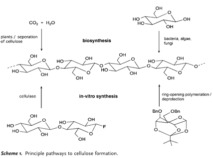
Figure 1. Pathways to cellulose formation. Adopted from Dieter K, et al. [11].
Solid-state structures of native cellulose
As shown in Figure 1, the hydroxy groups of b-1,4-glucan cellulose are placed at positions C2 and C3 (secondary, equatorial) as well as C6 (primary) [12]. The CH2OH side group is arranged in a trans-gauche position relative to the O5C5 and C4C5 bonds. As a result of the supramolecular structure of cellulose, the solid state is represented by areas of both high order (crystalline) and low order (amorphous).
In the 1980s, 13C-CP/MAS NMR spectroscopy was used in the initial discovery that native cellulose is present in two different crystalline cellulose I modifications (Ia and Ib), which can be found alongside each other; the Ia/Ib ratio depends on the origin of the cellulose [13]. Investigations with electron microbeam diffraction and combined X-ray and neutron diffraction recently revealed the corresponding crystalline structures to have triclinic (Ia) and monoclinic (Ib) unit cells [14,15].
Figure 2 shows a schematic representation of the Ib crystal structure. In the side view (Figure 2b) of the central chains of a unit cell, two intra molecular, chain-stiffening hydrogen bonds are revealed. Notably, one of the most recent reports on the Ib structure [16] describes different conformations for neighboring chains as well as different H-bonding systems inside neighboring molecular layers. Apart from the thermodynamically less stable cellulose I, cellulose may occur in other crystal structures (cellulose II, III, and IV) [17], of which cellulose II (Figure 2) is the most stable structure of technical relevance. It can be formed from cellulose I by treatment with aqueous sodium hydroxide (mercerization) or by dissolution of the cellulose and subsequent precipitation/regeneration, as is done in the formation of fiber and film. This monoclinic crystal structure [18] with two antiparallel chains in the unit cell is characterized by the specific unit cell geometry with a modified H-bonding system. The alkalization of cellulose is of considerable importance to commercial-scale cellulose production as a method for increasing the reactivity (activation) of subsequent reactions as well as for the mercerization of cotton. Depending on the concentration of lye, the temperature, and mechanical load, it is possible to convert cellulose I into various crystalline alkali forms, each with a different crystal structure and variable NaOH and water content [19] All forms will then convert into crystalline “hydrato cellulose” (water cellulose) during washout, and to cellulose II through drying.
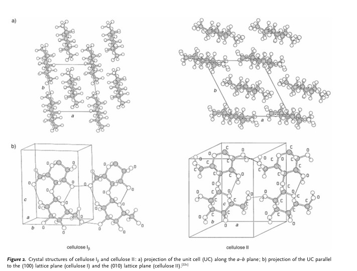
Figure 2. Crystal structure of cellulose 1 and cellulose II (a) Projection of the unit cell along the a-b plane (b) Projection of the UC parallel to the (100) lattice plane (cellulose 1) and the (010) lattice plane (cellulose II). Adopted from Zugernmaier P. [19].
Principles of solution electrospinning
Electrospinning is one of the most versatile fabrication techniques for making cellulose-based biomaterials for pollution cleanup. It produces nonwoven nanofiber mats with huge surface area, tunable porosity, and easy functionalization Electrospinning is one of the most versatile fabrication techniques for making cellulose-based biomaterials for pollution cleanup. It produces nonwoven nanofiber mats with huge surface area, tunable porosity, and easy functionalization. Among fabrication techniques, electrospinning stands out for environmental remediation due to its ability to produce cellulose-based nanofiber membranes with specific surface areas exceeding 40 m²/g and porosities >90%, enabling rapid adsorption of heavy metals, dyes, and emerging contaminants. Unlike beads or monoliths, electrospun mats combine low pressure drop with high accessibility of functional groups, making them suitable for point-of-use filters and continuous flow systems. However, challenges in wet mechanical stability, cost-effective scale-up, and anti-fouling performance in real wastewater remain unresolved.
Electrospinning is a unique technique that relies on the application of an electrostatic field to generate ultrafine fibers [20]. Generally, this process uses a setup consisting of four main components, as shown in Figure 3: a high-voltage power supply, a syringe pump, a spinneret (a syringe with a blunt-tip needle), and a fiber collector. In this process, a polymer is dissolved in a highly volatile solvent which is ejected from a syringe at a constant/controllable rate via the syringe pump [21]. Electrospinning is a unique technique that relies on the application of an electrostatic field to generate ultrafine fibers [22]. Generally, this process uses a straightforward setup consisting of four main components, as shown in Figure 3: a high-voltage power supply, a syringe pump, a spinneret (a syringe with a blunt-tip needle), and a fiber collector. In this process, a polymer is dissolved in a highly volatile solvent which is ejected from a syringe at a constant rate via the syringe pump. Due to the electrostatic force applied, a separation of positive and negative charges occurs within the liquid and charges of the same sign as the needle’s polarity move toward the surface, resulting in the formation of a charged polymer droplet at the needle’s tip [23]. By increasing the intensity of the electrostatic field, the surface charges density on the droplet rises, leading to enhanced mutual charge repulsion on the liquid’s surface. This, in turn, causes an expansion of the droplet’s surface area, mitigating repulsion. Consequently, the drop shape changes to a Taylor cone. Ultimately, the electrostatic repulsion overcomes surface tension, and a jet emerges, which is rapidly moving toward the collector [24]. As the jet progresses towards the collector, the polymer solution elongates and undergoes a whipping phenomenon, while the solvent undergoes evaporation. These processes collectively result in the formation of very small fibers [25].
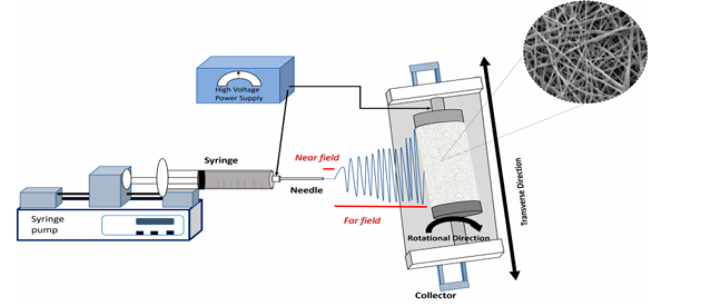
Figure 3. Schematic representation of a solution electrospinning setup. Adopted from Bonakdar MA, et al. [25].
There are four steps associated with the electrospinning procedure: the formation of a taylor cone at the needle’s tip, the ejection of the charged jet in a straight line, the stretching of the jet into finer diameters and the growth of physical instability, and finally, fiber solidification and deposition on the collector [26]. A well-formed Taylor cone is crucial for establishing a stable electrospinning process which controls the diameter and morphology of nanofibers. Irregular or unstable Taylor cones can lead to non-uniform nanofibers or even the formation of beads. This relationship can be valuable in optimizing the electrospinning process and improving the quality of the produced nanofibers. The jet emerging from the Taylor cone initially moves in a nearly straight line. This specific segment, often of short length, is designated as the near-field region. The velocity, length and diameter of the jet within the straight segment was studied by several research groups [27]. However, even a small perturbation at this stage can disrupt the straight trajectory, leading to instability. This instability can easily arise due to electrostatic repulsion among the surface charges on the jet as it enters the far-field regime [28]. This electrically charged jet can undergo three types of physical instabilities, which affect the size and geometry of the electrospun fibers. The first is the axisymmetric Rayleigh instability (jet centerline). The second is also an axisymmetric instability and the third, which is known as a whipping instability, is non-axisymmetric. The Rayleigh instability leads to jet breakup and the formation of a beaded fiber. The high surface tension and low viscosity of the solution contribute to the occurrence of this instability, which can be suppressed by a higher electric field or by increasing the polymer concentration in the solution. Electrospinning of a 4 wt.% poly(3-hydroxybutyrate-co-3-hydroxyvalerate) PHBV solution at 10 kV produced fibers with beads initially featuring a 1.5 µm fiber diameter with an average bead size of 14 µm. However, increasing the voltage to 30 kV while keeping the other parameters constant resulted in fibers with uniform diameters of 1.5 µm. The second type of instability happens in a stronger electric field than the first type due to electrostatic repulsion between the jet surface charges leading to the generation of a series of loops and a coil with numerous turns around the original direction. This effect causes the thinning and elongation of the jet [29]. Electrospinning gives cellulose a structural advantage no other method matches: nano size + handleability. For environmental remediation, it’s the best way to turn cellulose into high-flux, high-capacity membranes. The bottleneck now is not performance in DI water – it’s wet strength, cost, and proving it works in landfill leachate for 6 months.
Ultrasonication (US) or High Shear Homogenization (HSH)
Ultrasonication and high-shear homogenization are pivotal for converting bulk cellulose into nano fibrillated structures with surface areas >100 m²/g, a prerequisite for high-capacity sorbents. US achieves superior defibrillation via acoustic cavitation, producing CNF with diameters <20 nm and Pb²⁺ capacities of 350 mg/g, but suffers from high specific energy demand >1000 kWh/ton. HSH offers a scalable alternative, generating MFC at 100–500 kWh/ton, albeit with broader size distribution and lower adsorption capacity. Both techniques are essential for dispersing metal oxides, MOFs, and GO into cellulose matrices, preventing agglomeration and maintaining active surface area. Beyond material synthesis, US directly enhances remediation by desorbing pollutants from soils and regenerating spent sorbents via cavitation. Future work must address energy-cost trade-offs, equipment wear in real matrices, and the environmental fate of US-generated cellulose nanoparticles. One of the advantages is the reduced shear stress, while disadvantages consist of potential metal contamination and physical instability like particle growth upon storage.
The ultrasonication (US) technique is a dispersing technique, which was used for the production of solid lipid nano dispersion [30]. The US based on the mechanism of cavitation. In the first step, the drug was added to previously melt solid lipid. In the second step, the heated aqueous phase (heated to the same temperature) was added to the melted lipid and emulsified by probe sonication or by using a high-speed stirrer or aqueous phase added to the lipid phase drop by drop followed by magnetic stirring. The obtained pre-emulsion was ultrasonicated using a probe and a sonicator with a water bath (at 0oC). To prevent recrystallization during the process, the production temperature is kept at least 5oC above the lipid melting point. The obtained nano emulsion (o/w) was filtered through a 0.45 μm membrane to remove impurities carried in during the US. Then they obtained SLN is stored at 4oC. To increase the stability of the formulation, was lyophilized by a lyophilizer to obtain freeze-dried powder and sometimes mannitol (5%) was added into SLNs as cryoprotector.
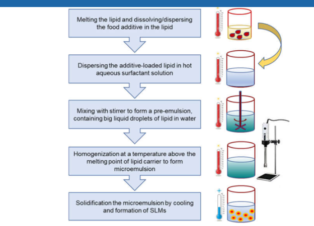
Figure 4. Process flow for the production of solid lipid microparticles.
Types of nanomaterial techniques used in agrochemicals
Electrospinning
Electrospinning serves as a bridging technology that transforms cellulose from a low-surface-area biopolymer into high-performance nanoarchitectures, enabling rapid, selective, and low-energy remediation. Its unique ability to combine nanoscale diffusion, membrane-level flux, and in-situ functionalization in a single continuous process makes it indispensable for next-generation water, air, and soil treatment media. Despite superior kinetics and flux, electrospun cellulose membranes face translational barriers: wet strength below 1 MPa limits module lifetime, solvent-intensive CA processing challenges green claims, and fouling in real matrices reduces service life to weeks. Future research must prioritize green solvent systems such as aqueous NaOH/urea, bio-based crosslinkers, and roll-to-roll needleless spinning to achieve <$5/m² cost targets. Standardized testing in complex waters and cradle-to-grave LCA are required to validate sustainability over granular activated carbon.
Electrospinning is a versatile and widely used technique for fabricating nanofibers from a variety of materials, including polymers, ceramics, and composites. The process involves the use of an electric field to draw and stretch a polymer solution or melt into nanoscale fibers, which are then deposited onto a collector substrate.
Principles of electrospinning
Electrospinning works on the principle of electrostatic attraction, where an electric field is applied between a spinneret (typically a needle) and a collector substrate. The polymer solution or melt is pumped through the spinneret, creating a droplet at the tip. When the electric field strength overcomes the surface tension of the droplet, a Taylor cone is formed, and a jet of polymer solution is ejected towards the collector. As the jet travels, the solvent evaporates, and the polymer solidifies into a nanofiber.
Electrospinning is a technique that has been used over the years to produce polymer fibers, although at a very low rates when compared with conventional spinning methods. The most preferred method for fiber production was melt spinning, although one of the limitations was the inability to produce fiber diameters in nanometer range [31-33]. In electrospinning, microfibers are produced to nanofibers using polymer solutions at atmospheric pressure and temperature. There are two setups involved in electrospinning devices. They include the horizontal and vertical [34]. There are three main components of the electrospinning device which include the power supply, syringe and collector [35-37].
Table 1. A simplified version of different techniques used in nanofiber production: advantages and disadvantages [37]
|
Technique |
Advantage |
Disadvantage |
|
Electrospinning |
Simple, cost efficient, easy to scale up, ability to fabricate fibers to the nm scale. |
Formation of jet instability, toxic solvents are used. |
|
Solution spinning |
Production rate is high, suitable for the production of both aligned and random fibers |
Toxic solvents, time consuming |
|
Force spinning |
Simple, produces high nanofibers |
High temperature |
|
Melt spinning |
Does not involve toxic solvents |
Produces low nanofibers output. |
Electrospinning is a technique that applies the top-down principle which is used to process micro and nanometer-sized materials [38]. Electrospinning equipment setup is illustrated in Figure 5. It consists of an injection system, syringe pump and a controlled flux. The infusion pump consists of a plastic syringe and a needle. The high voltage power supply provides a high voltage generation (0-30 kv).
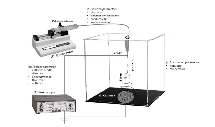
Figure 5. Schematic representation of the electrospinning equipment. Adopted from Hassan MI, et al. [39].
Wide range of sizes and shapes are produced when the process parameters are adjusted. There are three categories of the process parameters: solution, process and ambient.
a. Solution parameters: They include viscosity, solution evaporation, electrical conductivity and polymer concentration. There is a direct relationship between the viscosity and polymer concentration. Increase in concentration, increases the fiber diameter of the fiber.
b. Process parameters: This consist of the voltage, rate of solution fed, nozzle tip and types of collectors [40]. The surface charge on the electrospinning jet is being supplied by the applied voltage. Some of the spinning parameters such as the viscosity, voltage and feed rate affect the drop starting shape. The function of the collector is to serve as a conductive substrate for the charged nanofibers.
c. Environmental parameters: The diameter and morphology of the nanofibers are affected by mostly the humidity and temperature. The challenge associated with the factor is the use of toxic solvents which causes the cabinet to be exhausted.
Table 2. Electrospinning parameters
|
Solution |
Process |
Ambient |
|||
|
Cause |
Effect |
Cause |
Effect |
Cause |
Effect |
|
Increase concentration |
Higher diameter |
Increase voltage |
Lower diameter |
Increase temperature |
Lower diameter |
|
Increase viscosity |
Higher diameter |
Increase gap |
Lower diameter |
Increased humidity |
No effect |
|
Increase conductivity |
Lower diameter |
Increase flow rate |
Lower diameter |
||
High-shear homogenization
High-shear homogenization serves as the primary scalable technology for converting low-value cellulosic biomass into micro fibrillated cellulose sorbents and for dispersing functional nanoparticles into remediation composites. While yielding broader fiber distributions than ultrasonication, HSH operates continuously at 100–500 kWh/ton, making it the only economically viable route to ton-scale production of cellulose-based oil sorbents, flocculants, and filter aids. High-shear homogenization is a widely used technique in various industries, including pharmaceuticals, food, cosmetics, and biotechnology, for the production of stable emulsions, suspensions, and dispersions. The process involves the application of intense mechanical energy to break down particles or droplets into smaller sizes, resulting in a uniform and stable mixture [41].
Principles of High-Shear Homogenization
High-shear homogenization works on the principle of generating high shear forces to break down particles or droplets. This is achieved through the use of a rotor-stator assembly, where the rotor rotates at high speed, creating a region of high shear stress between the rotor and stator. The mixture is forced through this narrow gap, resulting in the breakdown of particles or droplets into smaller sizes.
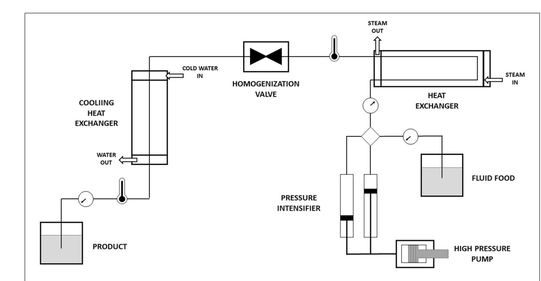
Figure 6. Schematic representation of high-shear homogenization. Adopted from Victoria N, et al. [41].
A high shear homogenizer (HSMs) consists of a high rotor tip speed, within the range of 10-50 m/s [42]. The use of high shear homogenizer has cut across various fields of agriculture, food manufacturing and chemical reaction processes. There are three categories of HSMs in terms of applications.
Liquid-liquid emulsification: They are used in the agrochemical industries to produce emulsions that have narrow droplet size distribution.
Solid-liquid suspensions: This is used to obtain nanoparticles suspensions that are stable and uniform. There are three different mechanisms that enhance the breakdown of capitals. They include erosion, rupture and scattering.
Chemical reactions: Chemical reaction process can be intensified using HSM. A better understanding of the reaction kinetics is vital as it helps to monitor the reactants conversion and target product.
Aqueous counter collision
Aqueous Counter Collision serves as a chemical-free, top-down nano fibrillation technology that produces uniquely long, mechanically robust, and surface-pristine cellulose nanofibers. These attributes translate to environmental materials with superior wet strength, tunable surface chemistry, and ultra-high capacity for oil, metals, and emerging contaminants, bridging the gap between lab-scale US-CNF performance and industrial-scale HSH-MFC economics. Aqueous counter collision (ACC) is a novel and eco-friendly technique used for the production of nanofibers and nanoparticles from various materials, including cellulose, polymers, and composites. The process involves the collision of two high-pressure jets of a suspension or solution, resulting in the breakdown of particles into smaller sizes.
Principles of aqueous counter collision
ACC works on the principle of generating high-energy collisions between two opposing jets of a suspension or solution. The collision creates intense shear forces, cavitation, and turbulence, leading to the breakdown of particles into smaller sizes. The process is typically carried out in an aqueous environment, making it an environmentally friendly alternative to traditional methods [43].
Figure 7. Aqueous counter collision system. Adopted from Kose R, et al. [44].
The entrained particles are exposed to a high shear whenever there is a change in velocity. There are two major advantages associated with the ACC technique: 100 % yield production and production of well-structured fibrils. Microcrystalline cellulose (MCC) is one of the starting materials used in ACC, due to the small channel size [43,44].
Cryocrushing
Cryocrushing serves as a low-chemical, low-energy mechanical pretreatment that embrittles cellulose fibers and increases surface accessibility without reducing molecular weight. While it does not produce nanofibers, it significantly reduces the energy demand of subsequent HSH/US/ACC steps and generates micro-scale powders suitable for bulk remediation applications such as oil sorption, soil amendment, and filter aids where nanoscale area is not essential and cost, biodegradability, and ease of recovery are prioritized. Cryocrushing is a mechanical process used to reduce the size of materials, including polymers, metals, and composites, into fine powders or nanoparticles. The process involves the use of cryogenic temperatures, typically liquid nitrogen, to embrittle the material, making it susceptible to crushing and grinding.
Principles of Cryocrushing
Cryocrushing works on the principle of thermally induced embrittlement, where the material is cooled to a temperature below its glass transition temperature (Tg), making it brittle and prone to fracture. The embrittled material is then subjected to mechanical forces, such as grinding or crushing, to break it down into smaller particles [45,46].
Challenges and Future Prospects
Despite the promising applications of cellulose-based biomaterials in environmental remediation and agricultural sustainability, several challenges need to be addressed to fully realize their potential.
Challenges
Scalability: Scaling up the fabrication techniques for large-scale production remains a significant challenge. Current methods are often limited to laboratory-scale production, and scaling up while maintaining quality and consistency is crucial.
Cost-effectiveness: Reducing the cost of production to make cellulose-based biomaterials competitive with synthetic materials is essential. The cost of raw materials, processing, and functionalization needs to be optimized.
Regulatory issues: Addressing regulatory issues related to the use of cellulose-based biomaterials in agriculture and environmental remediation is necessary. Clear guidelines and standards need to be established.
Performance and durability: Ensuring the performance and durability of cellulose-based biomaterials in various environmental conditions is critical. Factors like degradation, stability, and interactions with other substances need to be considered.
Future Prospects
Sustainable agriculture: Cellulose-based biomaterials can contribute to sustainable agriculture by improving soil health, reducing chemical usage, and promoting eco-friendly practices.
Environmental remediation: Cellulose-based biomaterials can be used for remediation of contaminated soils and waters, offering a cost-effective and environmentally friendly solution.
Circular economy: Cellulose-based biomaterials can play a key role in the circular economy by utilizing biomass waste and reducing plastic usage.
Advanced applications: Research on advanced applications, such as nanocellulose-based composites, aerogels, and membranes, is expected to expand the scope of cellulose-based biomaterials.
By addressing these challenges and exploring new opportunities, cellulose-based biomaterials can become a vital component of sustainable development and environmental stewardship.
CONCLUSION
cellulose-based biomaterials have shown great promise for sustainable agriculture and environmental remediation. Their unique properties, such as biodegradability, biocompatibility, and renewability, make them an attractive alternative to synthetic materials. Various fabrication techniques, including electrospinning allow for the production of cellulose-based biomaterials with tailored properties. Despite challenges like scalability and cost-effectiveness, the future prospects of cellulose-based biomaterials are bright, with potential applications in sustainable agriculture, environmental remediation, and circular economy.
ACKNOWLEDGEMENTS
None.
CONFLICT OF INTEREST
No conflict of interest is associated with this work.
CONTRIBUTIONS OF AUTHORS
Chekwube A. Ezegbe: Conceptualization, writing, revision; Obioma R. Emeka-Obi: Conceptualization, writing, revision; Kosisochukwu A. Emeagwali: Conceptualization, writing, revision; Ezinne C. Okorafor: writing, revision; John I Osaro: writing, revision.
REFERENCES
- Klemm D, Heublein B, Fink HP, Bohn A. (2005). Cellulose: fascinating biopolymer and sustainable raw material. Angew Chem Int Ed Engl. 44(22):3358-3393.
- Moon RJ, Martini A, Nairn J, Simonsen J, Youngblood J. (2011). Cellulose nanomaterials review: structure, properties and nanocomposites. Chem Soc Rev. 40(7):3941-3994.
- Ezegbe CA, Ezegbe AG, Okorafor EC, Ogbonna EE. (2025). Mini Review on the Morphological and Microanalysis Characterization of Chitosan Nanocomposites Using Scanning Electron Microscopy. Mathews J Pharma Sci. 9(3):52.
- Hubbe MA, Rojas OJ, Lucia LA, Sain M. (2008). Cellulosic nanocomposites: A review. BioResources. 3(3):929-980.
- Eichhorn SJ, Dufresne A, Aranguren M, Marcovich NE, Capadona JR, Rowan SJ, et al. (2010). Review: current international research into cellulose nanofibres and nanocomposites. J Mater Sci. 45:1-33.
- Klemm D, Heublein B, Fink HP, Bohn A. (2005). Cellulose: fascinating biopolymer and sustainable raw material. Angew Chem Int Ed Engl. 44(22):3358-3393.
- Srivastava RK. (2017). Electrospinning of Patterned and 3D Nanofibers. In Electrospun Nanofibers; Woodhead Publishing: Cambridge, UK. pp. 399-447.
- Xue J, Wu T, Dai Y, Xia Y. (2019). Electrospinning and Electrospun Nanofibers: Methods, Materials, and Applications. Chem Rev. 119(8):5298-5415.
- Luo CJ, Stoyanov SD, Stride E, Pelan E, Edirisinghe M. (2012). Electrospinning versus fibre production methods: from specifics to technological convergence. Chem Soc Rev. 41(13):4708-4735.
- Persano L, Camposeo A, Tekmen C, Pisignano D. (2013). Industrial Upscaling of Electrospinning and Applications of Polymer Nanofibers: A Review. Macromol Mater Eng. 298(5):504-520.
- Reneker DH, Chun I. (1996). Nanometre Diameter Fibres of Polymer, Produced by Electrospinning. Nanotechnology. 7:216-223.
- Reneker DH, Yarin AL, Fong H, Koombhongse S. (2000). Bending Instability of Electrically Charged Liquid Jets of Polymer Solutions in Electrospinning. J Appl Phys. 87(9):4531-4547.
- Wang C, Wang J, Zeng L, Qiao Z, Liu X, Liu H, et al. (2019). Fabrication of Electrospun Polymer Nanofibers with Diverse Morphologies. Molecules. 24(5):834.
- Zugenmaier P. (2001). The Structures of Cellulose. Prog Polym Sci. 26:1341-1417.
- Kumar TSM, Kumar KS, Rajini N, Siengchin S, Ayrilmis N, Rajulu AV. (2019). A comprehensive review of electrospun nanofibers: Food and packaging perspective. Compos Part B Eng. 175(3):107074.
- Ding J, Zhang J, Li J, Li D, Xiao C, Xiao H, et al. (2019). Electrospun polymer biomaterials. Prog Polym Sci. 90:1-34.
- Liu L, Xu W, Ding Y, Agarwal S, Greiner A, Duan G. (2020). A review of smart electrospun fibers toward textiles. Compos Commun. 22:100506.
- Baji A, Mai YW, Wong SC, Abtahi M, Chen P. (2010). Electrospinning of Polymer Nanofibers: Effects on Oriented Morphology, Structures and Tensile Properties. Compos Sci Technol. 70(5):703-718.
- Subbiah T, Bhat GS, Tock RW, Parameswaran S, Ramkumar SS. (2005). Electrospinning of Nanofibers. J Appl Polym Sci. 96(2):557-569.
- Bonakdar MA, Hamdi O, Nazarenko Y, Ariya PA, Rodrigue D. (2023). Highly porous biobased membranes via electrospinning of PBS and CTAB. Polymer. 280:126045.
- Mitchell GR, Ahn KH, Davis FJ. (2011). The Potential of Electrospinning in Rapid Manufacturing Processes: The Fundamentals of Electrospinning, Key Process Parameters, Materials and Potential Application in Rapid Manufacturing Are Presented in This Paper. Virtual Phys Prototyp. 6(2):63-77.
- Garg K, Bowlin GL. (2011). Electrospinning jets and nanofibrous structures. Biomicrofluidics. 5(1):13403.
- Ballengee J, Pintauro P. (2010). Morphological Control of Electrospun Nafion Nanofiber Mats. ECS Trans. 33(1):647-658.
- Nahum V, Domb AJ. (2021). Recent Developments in Solid Lipid Microparticles for Food Ingredients Delivery. Foods. 10(2):400.
- Ajiboye AL, Nandi U, Galli M, Trivedi V. (2021). Olanzapine Loaded Nanostructured Lipid Carriers via High Shear Homogenization and Ultrasonication. Sci Pharm. 89(2): 25.
- Teo WE, Ramakrishna S. (2006). A review on electrospinning design and nanofibre assemblies. Nanotechnology. 17(14):R89-R106.
- Pillay V, Dott C, Choonara YE, Tyagi C, Tomar L, Kumar P, et al. (2013). A review of the effect of processing variables on the fabrication of electrospun nanofibers for drug delivery applications. J Nanomater. 2013:789289.
- Saleem H, Trabzon L, Kilic A, Zaidi SJ. (2020). Recent advances in nanofibrous membranes: production and applications in water treatment and desalination. Desalination. 478:114178.
- Dalton PD, Klinkhammer K, Salber J, Klee D, Möller M. (2006). Direct in vitro electrospinning with polymer melts. Biomacromolecules. 7(3):686-690.
- Xue J, Wu T, Dai Y, Xia Y. (2019). Electrospinning and Electrospun Nanofibers: Methods, Materials, and Applications. Chem Rev. 119(8):5298-5415.
- Liao Y, Loh CH, Tian M, Wang R, Fane AG. (2018). Progress in electrospun polymeric nanofibrous membranes for water treatment: fabrication, modification and applications. Prog Polym Sci. 77:69-94.
- Senthil T, George G, Srinivasan A. (2016). Electrospinning: from Fundamentals to Applications. In: Advances in Polymer Materials and Technology. 1st edn. CRC Press, Boca Raton, USA. pp. 171-240.
- Lee JS, Choi KH, Ghim HD, Kim SS, Chun DH, Kim HY, et al. (2004). Role of molecular weight of atactic poly (vinyl alcohol) (PVA) in the structure and properties of PVA nanofabric prepared by electrospinning. J Appl Polym Sci. 93(4):1638-1646.
- Hassan MI, Anke K. (2020). A review on electrospun polymeric nanofibers production parameters and potential applications. Polymer Testing. 90:106647.
- Lin Y, Yao Y, Yang X, Wei N, Li X, Gong P, et al. (2008). Preparation of poly (ether sulfone) nanofibers by gas-jet/electrospinning. J Appl Polym Sci. 107(2):909-917.
- Victoria N, Abraham JD. (2021). Recent Development in solid lipid Microparticles for food ingredients Delivery. Foods. 10(2):400.
- Atiemo-Obeng VA, Calabrese RV. (2004). Rotor–stator mixing devices. In: Paul EL, Atiemo-Obeng VA, Kresta SM, (Eds.). Handbook of Industrial Mixing: Science and Practice. John Wiley & Sons, Inc, New Jersey, USA.pp. 479-505.
- Ninomiya K, Abe M, Tsukegi T, Kuroda K, Tsuge Y, Ogino C, et al. (2018). Lignocellulose nanofibers prepared by ionic liquid pretreatment and subsequent mechanical nanofibrillation of bagasse powder: Application to esterified bagasse/polypropylene composites. Carbohydr Polym. 182:8-14.
- Kose R, Mitani I, Kasai W, Kondo T. (2011). Nanocellulose as a Single Nanofiber Prepared from Pellicle Secreted by Gluconacetobacter Xylinus Using Aqueous Counter Collision. Biomacromolecules. 12(3):716-720.
- Chen W, Yu H, Liu Y, Hai Y, Zhang M, Chen P. (2011). Isolation and Characterization of Cellulose Nanofibers from Four Plant Cellulose Fibers Using a Chemical-Ultrasonic Process. Cellulose. 18(2):433-442.
- Wang B, Sain M, Oksman K. (2007). Study of Structural Morphology of Hemp Fiber from the Micro to the Nanoscale. Appl Compos Mater. 14(2):89-103.